

Jun 30 2018
Fabricating a Work Table
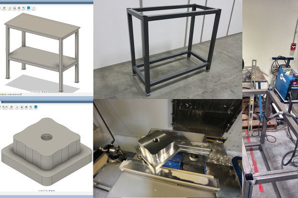
What a fucking horrible week. It's now official. The law of the land. We all have to live with gerrymandering while listening to the racist rants of a fucking Liar in Chief. After being pissed on all year, we get dumped on with a big sack of retirement shit. Oh, the table. TIG welded + CNC machined leveling foot. Yeah, for all you "patriotic" fuckers who like to shop at Harbor Freight, the Miller TIG welder used to weld the table is made in USA; the Haas CNC VMC used to machine the leveling foot is made in USA; the UNICOMP keyboard I am using to type this fucking sentence is also made in USA.
Mar 15 2018
Environment Sensor Board Version 2
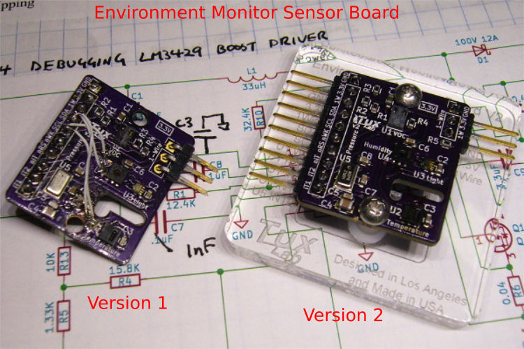
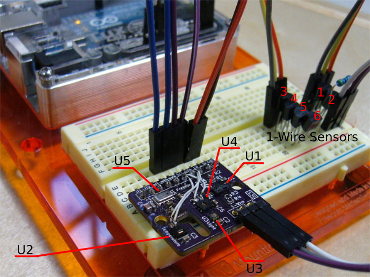
The i2c bus wiring mistakes of sensors U2 and U4 were corrected and the revised KiCAD layout file uploaded to OSHPark. The original sensor test program ran without any issues on the revised board. With the preliminary circuit and data acquisition program completed, the next step is to figure out the corresponding physical enclosure and continuous data collection.
Mar 08 2018
i2c bus debuggin with Saleae Logic Analyzer
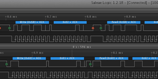
Normally i2c communication is fair straight forward. To communicate with a slave device, the master initiates a start signal follow by the hex address of the slave device. The slave acknowledges and wait for further instruction from the master.
The master then issues hex address commands to the slave and reads the responding bytes of data from the slave. The received bits of data are then converted to sensor reading based on the algorithm provided in the sensor datasheets.
A logic analyzer enables the user to see the actual digital bytes being sent and received on the i2c bus, as well as the actual physical analog signals of the i2c bus, thus allowing the user to more easily identify communication issues on the i2c bus.
Mar 02 2018
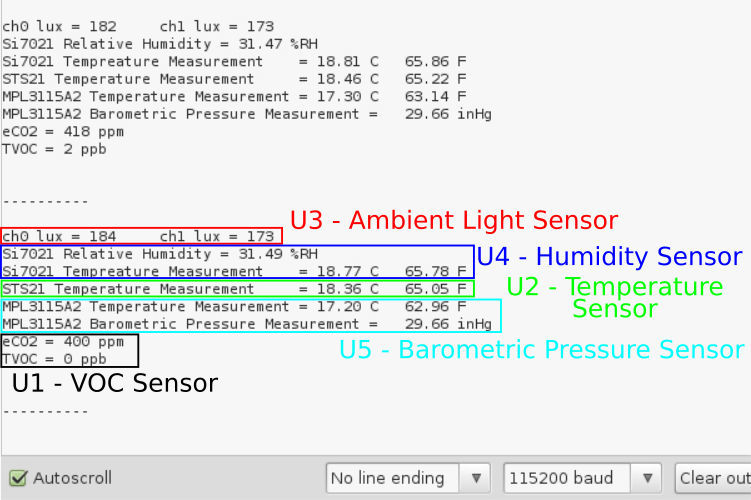
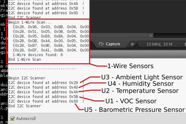
How was this obvious error missed, twice?
After the environment monitor board was assembled, a quick i2c bus scan showed only 3 of the 5 sensors. After a few minutes of head scratching and probing with the continuity meter on both the populated board and unpopulated PCB to check for shorts and open connection, the PCB assembly process seems okay. Yet, two sensors are still unresponsive.
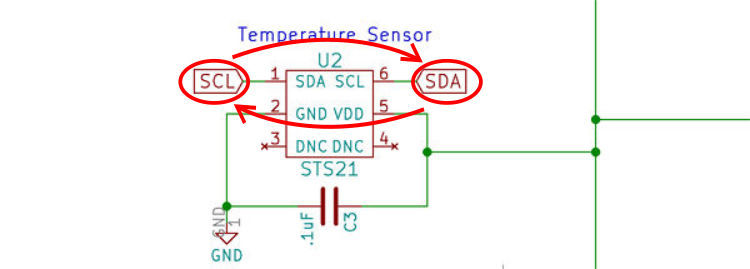
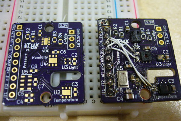
Double checking the schematic revealed that the i2c lines were reversed for the non-responding sensors. However, it was a salvageable mistake. The offending line traces were cut and new connections were made using 30awg wire wrap wires. The result was not pretty, but all 5 sensors show up on i2c bus scan.
Feb 28 2018
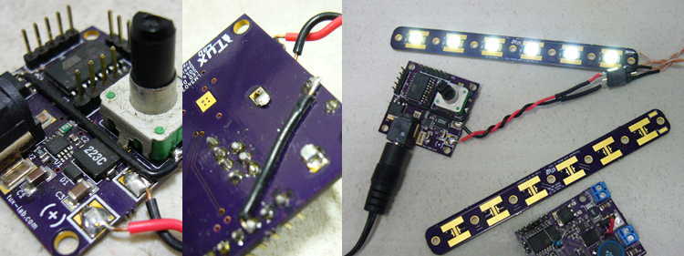
DIY SMT Assembly
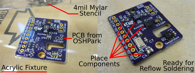
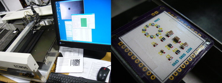
As expected, a package arrives from OSHPark 2 weeks after submitting the PCB layout, and the process of SMT assembly begins. . .
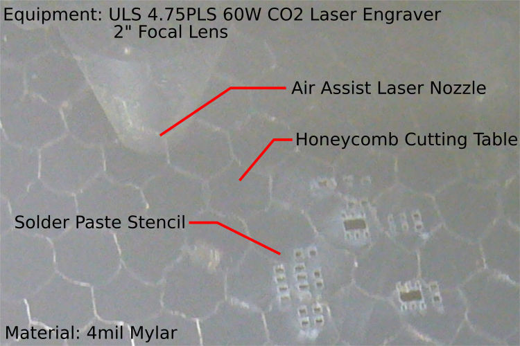
Solder paste stencil layout is exported from KiCAD and sent to the CO2 laser engraver. Typically, the solder paste mask is shrunk by 10% before exporting from KiCAD to avoid applying too much solder paste that caused bridging on smaller pads. Once solder paste has been applied, the various SMT components are placed manually. The populated PCB is then reflow soldered using a hotplate.
Feb 13 2018
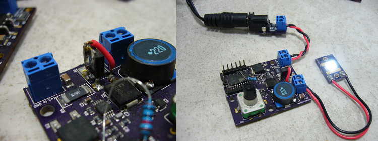
3.3V - 1.8V = 4 Hours
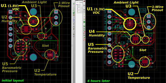
After a couple days of searching DigiKey for the various sensor ICs to populated the long delayed environment monitoring board, the Eizo monitors once again glow with the nurturing altruistic warmth of the open source community courtesy of KiCAD. A temporary reprieve from the heartbreaking, soul crushing, reality of modern American kleptocracy. Oh'...wait, about 3.3V - 1.8V = 4 Hours. . .
This board is a followup to the various sensor boards made with KiCAD from a few years ago, back when people lament the underachievement of an over promised presidency.... sorry, memory is such a volatile affair, back to the current reality....
So, first couple i2c sensor boards were made with single Si7021 humidity sensor and MPL3115A2 barometric pressure sensor. The little 6pin Si7021 was particularly easy to used and were used in a couple introduction to KiCAD meetups hosted in Tux-Lab, to show people how to use the datasheet to draw the KiCAD schematic symbols and create the corresponding KiCAD footprint. The Si7021 datasheet also serves as a good introduction on using the i2c bus to query for the humidity and temperature data bytes and using the provided algorithm for converting to human readable digits.
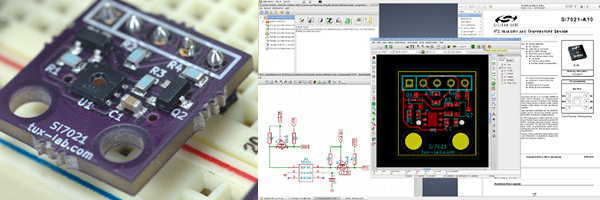
As a follow up, a few more sensors are added, mostly as a skill building exercise for interfacing multiple i2c devices and writing simple libraries using the datasheets. The slot above the temperature sensor is for trying out OSHPark's PCB slotting capability. The next iteration will minimize the slot pinch area to increase thermal isolation for the temperature sensing IC.
Prior to uploading the PCB layout to OSHPark, a final check discovered the VOC sensor IC has a maximum operating voltage of 1.8V, which necessitated a substitution for another VOC sensor IC that will function with 3.3V. Sadly, the new IC is not pin compatible and required an additional 4 hours to redo the PCB layout, hence 3.3V - 1.8V = 4 Hours. Haha. Well, considering that going from the previous 5V sensor board via a couple mosfet level shifter to the current native 3.3V board took a few years. Perhaps 4 hours is an improvement.

Nov 12 2017
MDC ECM96 Pick and Place Machine
Ever since we started designing PCB with KiCAD and receiving the underpopulated boards from OSHPark, we've always dreamed of acquiring a pick and place machine. However, . . . show details
Ever since we started using KiCAD to design PCB and receiving the underpopulated PCB from OSHPark, we've always dreamed of acquiring a pick and place machine. However, the cost of a new pick and place is prohibitively high. Once in a while, we'll see affordable used machines, but with questionable operational status, lack of included feeders, and unfamiliarity with pick machines in general, the risk was too great.
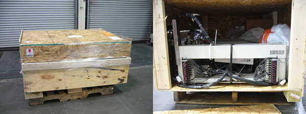
Finally we found a used machine made by MDC. The machine was made in 1996, but the previous owner was still operating it earlier this year and it comes withe manuals along with plenty of feeders.
A couple weeks later, the crate showed up. The crate was damaged in transit but the content looks okay. With the help from the former owners, we were able to get the machine up and running without too much trouble.
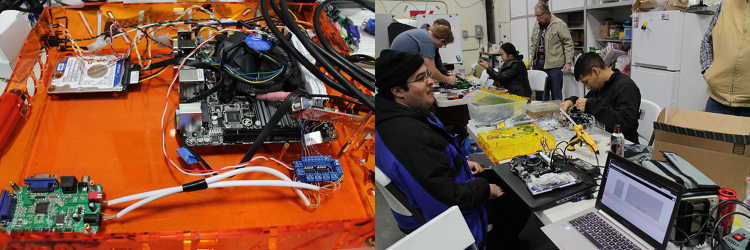
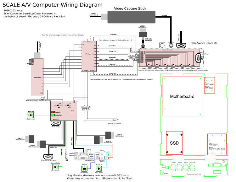
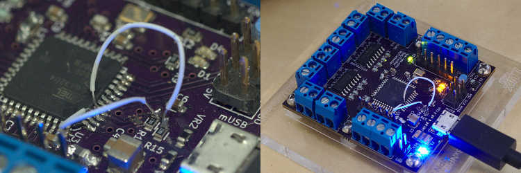
Mar 03 2017
SCaLE A/V Podium PC
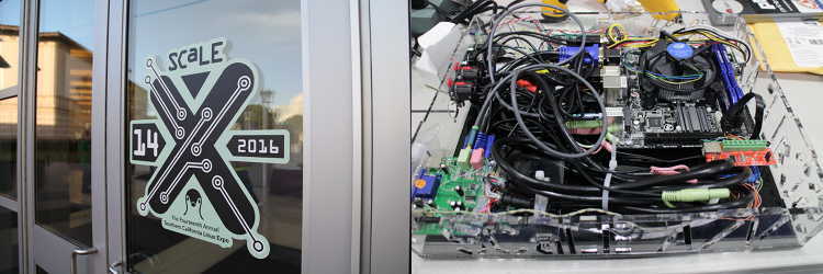
The selfless Linux spirit is one of the guiding principles for Tux-Lab, and for the last few years, SVGLUGers has gathered Tux-Lab to help with the various SCaLE Audio/Video team projects.
The selfless Linux spirit is one of the guiding principles for Tux-Lab, and for the last few years, SVGLUGers has gathered Tux-Lab to help with the various SCaLE Audio/Video team projects.
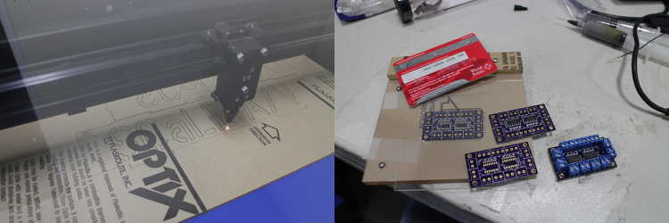
SCaLE A/V Podium PCs are placed in each conference room and remotely control to display conference messages and record the conference talks. At Tux-Lab, we laser cut the acrylic cases, design the NPN boards, and assembly the podium PCs.
Oct 28 2016
Debugging Electronics
To err is human, and we know we are definitely human. . . . show details
To err is human, and we know we are definitely human. Thanks to our oscilloscope, magnifying glasses, soldering and hot air station, and lot of perseverance and patience, something getting a non-working board back into working condition feels like divine euphoria.
Sometimes the errors are obvious and easy to fix. Other times, carelessly placing schematic components and ordering MOSFETs without paying attentions to the source gate drain pinouts, can lead to days and weeks of agonizing madness.
Jan 22 2016
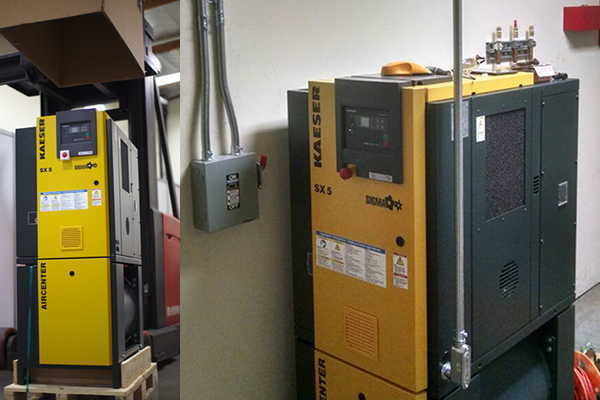
Kaeser AirCenter SX5
Installation of a Kaeser AirCenter SX5. It's a 5hp rotary . . . show details
Installation of a Kaeser AirCenter SX5. It's a 5hp rotary screw compressor, with an integrated air dryer, and rated at 21 cfm. It's compact enough to fit into the electrical room, and fairly quiet at 64dBA.